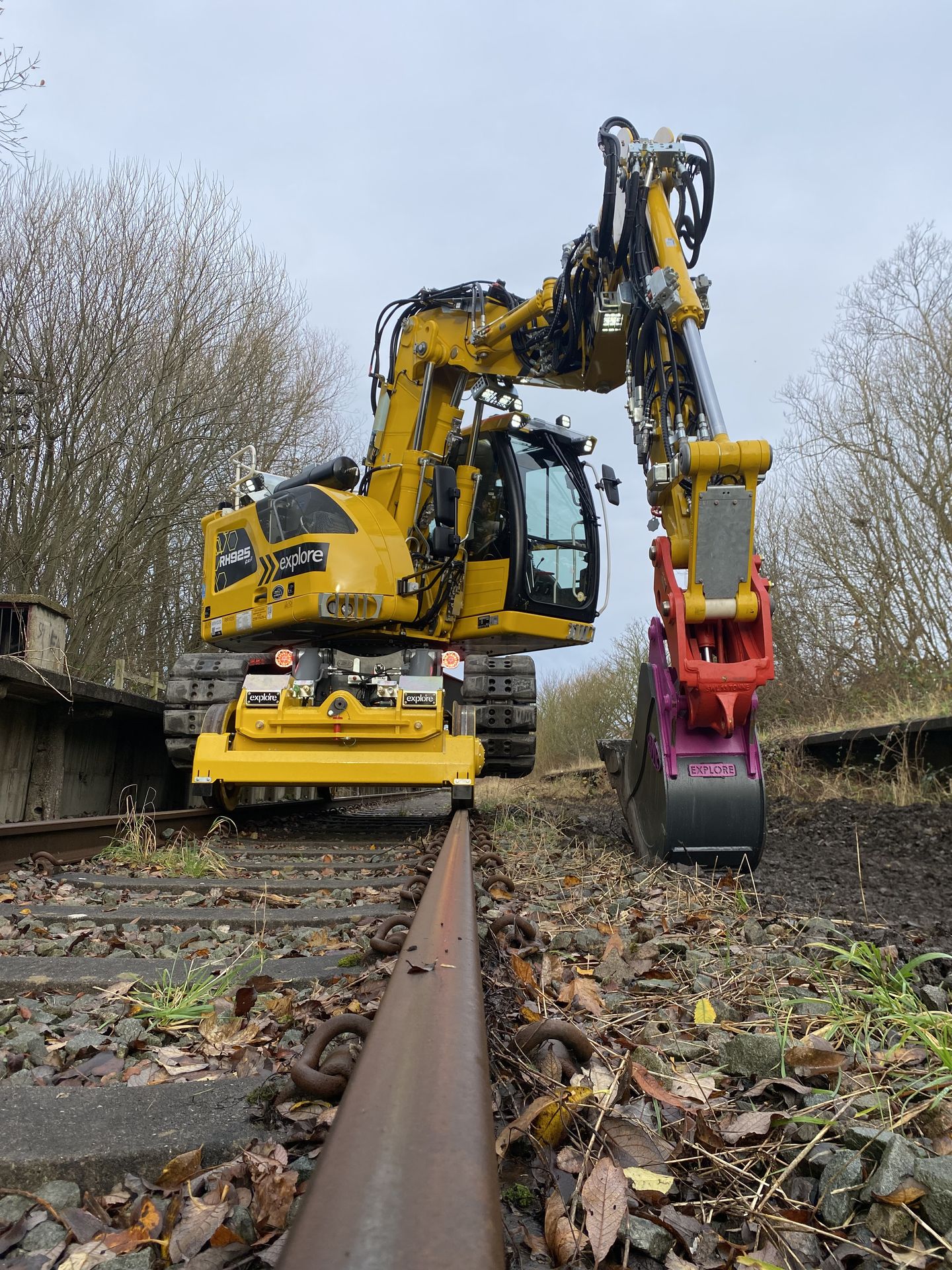
Development of the Liebherr RH925
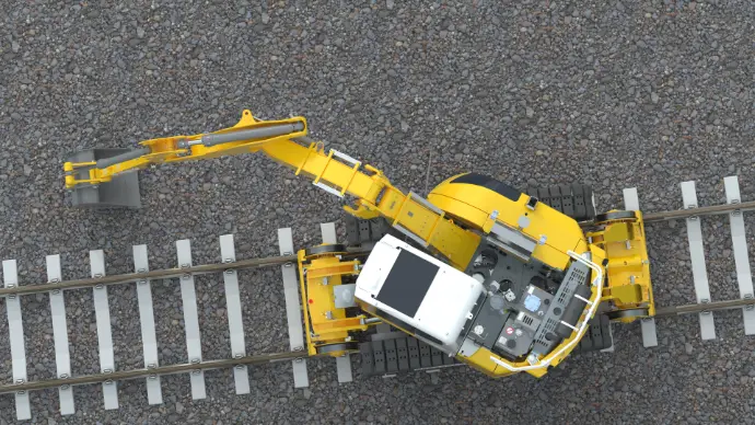
The high-level concept for the new machine was a mid-eight-tracked excavator. It was to be optimised for efficient digging in restricted areas and have a high lift capacity for the machine’s weight class.
While Allan J. Hargreaves Plant Engineers’ (AJH Plant’s) Liebherr R920 is class-leading for heavy lifting and digging, a smaller machine that is more manoeuvrable in tight spaces and more efficient and economical was required. The high-quality and advanced features of Liebherr machines have proved popular with AJH Plant’s customers, and so the Liebherr R914 compact was selected. AJH Plant has a close technical relationship with Liebherr GB and the Liebherr LFR factory, where the R914 machines are built. Liebherr therefore supplies AJH Plant with custom machines optimised for conversion to UK rail machines.
At 90kW, the R914 compact sits between the 72kW AJH Plant/Komatsu PC138 and the 110kW Liebherr R920.
Design and development - mechanical
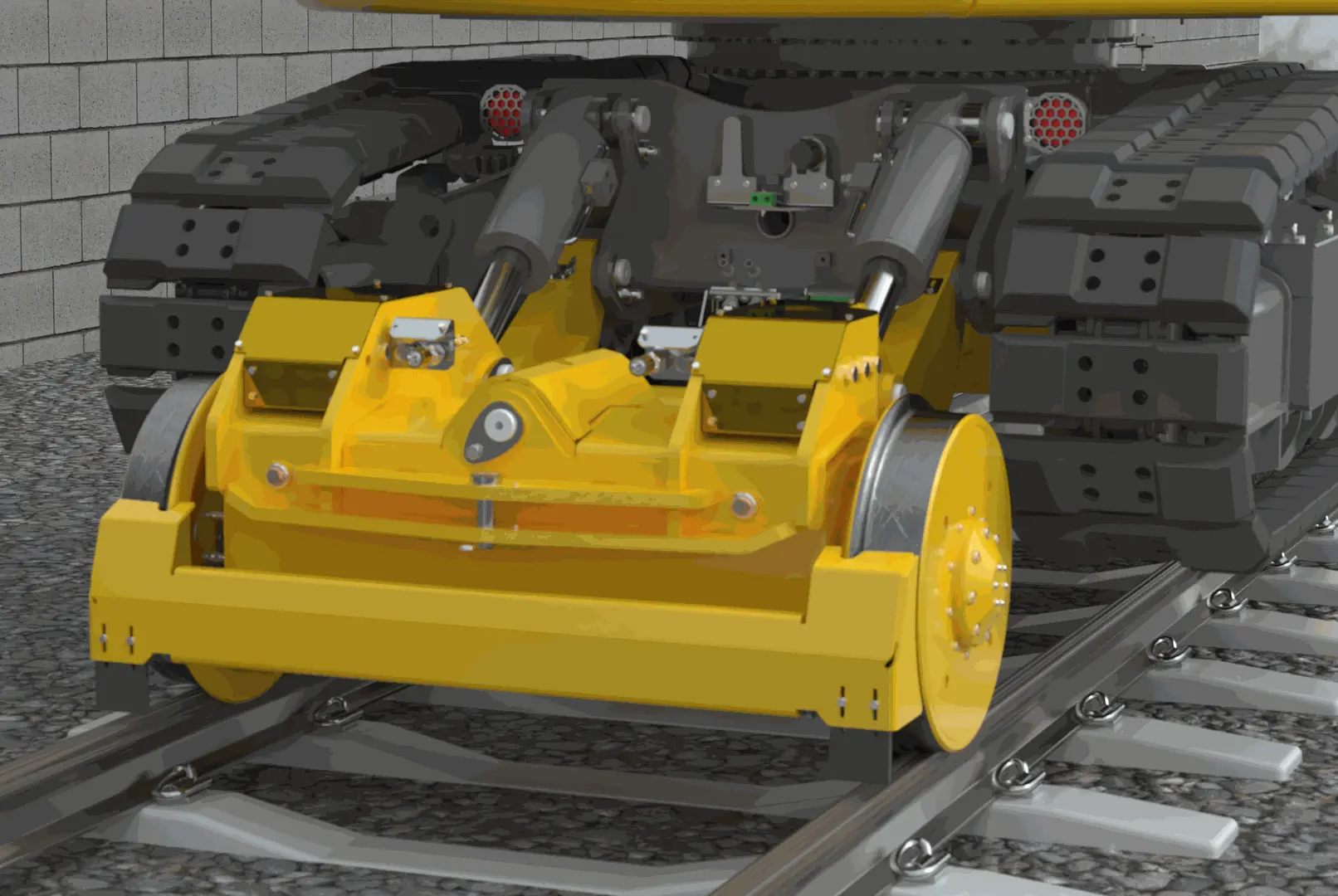
Like almost all road/rail excavators, the machine was designed with one fixed and one floating axle. With this three-point suspension system, the floating axle is allowed to pivot around a central pin when travelling, but is locked with hydraulic cylinders on either side when stationary, stiffening the machine and increasing lifting capacity.
The railgear is based on the Liebherr R920 concept, but is designed to be slightly smaller and lighter for the mid-weight RH925. 640mm wheels were chosen to maximise lift capacity without exceeding the maximum permissible wheel loads, while maintaining approach angles of more than 25 degrees. Liebherr is supplying the machines with blade-mount assemblies at both ends of the chassis, allowing easy integration of the railgear onto OEM fixtures. Self-lubricating Graphene-impregnated bushes are used on all linkages, meaning that only the rail wheel bearings require greasing.
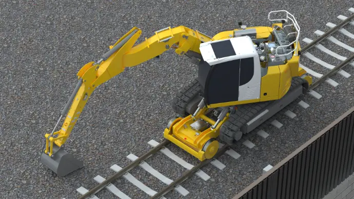
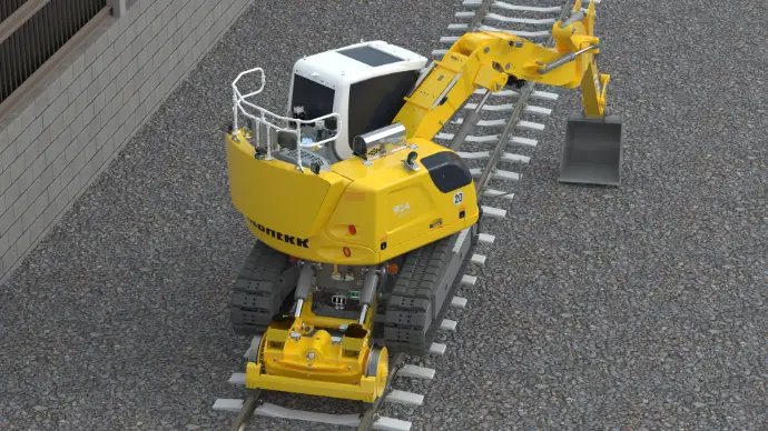
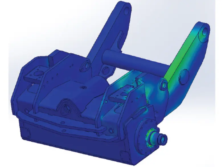
Tracked machines have inherently low centres of gravity, which improves stability both forward and backwards. As part of the rail conversion, the centre of gravity has been optimised by fitting an additional track frame weight and lifting the machine only enough to achieve lower sector gauge clearance, taking account of track sag.
The balance between heavy lifting and restricted-space digging is achieved through removable counterweight and offset-boom options. The piggyback counterweight can be fitted and removed by lifting it onto locating pins and then bolting it in place. This increases the machine’s mass by two tonnes and significantly increases its lifting capacity. When space is limited, removing the counterweight reduces the tail swing by 215mm.
The offset boom is a Liebherr OEM option, and with a 48-degree maximum offset angle, it provides the greatest digging versatility of the boom options, particularly for troughing and drainage. The OEM cab has ROPS certification up to 30 tonnes, meaning that even with the additional weight added by AJH Plant, the operator is protected in the unlikely event of a rollover.
Service braking is provided both hydrostatically and with a disc brake. Releasing the travel control will immediately apply hydrostatic braking, and by moving the brake controller forward, the operator can control how much disc brake force is applied and increase the hydrostatic brake force. This allows the operator to control the amount of service brake force applied to suit the gradient and railhead conditions.
The disc brake also acts as a digging brake. Whenever the machine is stationary, the brake automatically fully applies. Because it is designed to slow a moving vehicle, the service brake is well-suited to the highly dynamic loading of digging, whereas park brake packs can suffer from premature wear and failure under repeated dynamic loading.
Design and development -hydraulic
The machine has four variable-displacement hydraulic drive motors, each coupled to the rail wheel via a reduction gearbox and a multidisc park brake pack. The maximum displacement has been selected to provide sufficient torque for towing 80 tonnes while also providing a minimum 10,000-hour operating life. In travelling mode, sufficient flow is provided to the motors for the machine to reach 15mph.
The operator can switch drive modes between travel, creep, and work. Travel mode provides the full range of motor displacement and proportional drive demand, prioritising motor torque and speed. Creep mode limits the proportional drive demand, effectively limiting maximum speed; this allows driving at a very consistent speed for high-accuracy tasks. Work mode limits both the proportional drive demand and the motor's maximum displacement, thereby limiting the hydraulic flow taken by the drive system and ensuring that sufficient flow is available for attachments, while preventing changes in machine speed as attachment load increases and decreases. The settings are user-adjustable for work and creep modes, although default settings calibrated by AJH Plant provide a good balance of machine characteristics.
The machines have been designed with a bucket ram diverter, allowing hydraulic flow from the bucket to be directed to an additional service to power attachments.
Design and development - electrical and software
The AJH Plant control system is built around IFM hardware, with the main ECU communicating with input/output nodes via CAN bus. The current machines have been designed around an InTeEx RCI and high-performance MLD; however, a GKD system is offered as an option. InTeEx also uses IFM hardware for its systems, and AJH Plant has worked with InTeEx to integrate the two control systems as closely as possible. An Ethernet link between the two systems allows them to exchange input data, eliminating the need to wire inputs to both systems and reducing system complexity. The reversing camera is also integrated into the InTeEx screen, reducing the number of screens mounted inside the cab.
By intermittently sending small currents through the inputs and outputs, the AJH Plant control system monitors for short circuits, open circuits, and overloads. This gives the operator immediate warning of a fault and helps engineers quickly identify and fix the cause of faults.
Along with the usual boom position sensors, the knuckle on the offset boom is fitted with a rotary encoder to determine the exact position of the dipper end when the boom is offset. This ensures that the safe working load for lifting is always correct and that the machine cannot exceed virtual walls.
RFID tags are used to verify that the piggyback counterweight is fitted, enabling the RCI to automatically select the correct lifting duties and machine envelope. Four of these are used to meet the redundancy required to achieve Performance Level D.
To ensure efficient brake testing, the operator can perform a brake self-test. This can be done in less than three minutes, and is carried out in road mode, so it can be done before the machine is on-tracked. The results of all tests are logged in the control system for traceability. Like the manual brake torque test carried out on type 9B machines, the test works by using the hydraulic motor to apply a known pressure and displacement, and therefore a known torque, to each individual wheel with the brake applied. The machine speed sensor, a rotary encoder within the hydraulic motor, is then used to monitor wheel rotation and ensure that the brakes do not slip.
Design and development - remote access systems
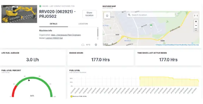
Integrated into the IFM-based control system is an IoT antenna that provides remote access to the machine. This allows customers to view current and historical machine data and enables AJH Plant engineers to perform remote diagnostics before an engineer arrives on-site.
All data is available to machine owners in AJH Plant’s web-based platform. The engine CAN bus has been wired into the IoT system, giving machine owners access to engine hours, engine idle and working time, AdBlue level and usage, fuel level and usage, coolant level and usage level, temperature, DPF soot load, DPF ash load, cancelled DPF regens, engine warning lamp status, oil level, oil temperature and pressure and engine torque and RPM.
Additionally, diagnostic information from AJH Plant’s control system and the InTeEx system is made available in the web platform. If faults are detected in either the AJH or InTeEx systems, they are uploaded to the web platform, and automated emails are sent to the AJH Plant so that engineers can diagnose the issue.
In addition to the diagnostic information provided in the web platform, AJH Plant can remotely view the control system screen. This enables advanced remote fault-finding and allows AJH to guide operators through features where machine familiarisation is an issue.
Optionally, oil quality sensors can be added to the machine, allowing condition-based oil changes and advanced warning of hydraulic faults. On the machine’s HMI and within the web platform, machine owners will be able to see an oil quality number, a red-amber-green oil condition status, and the predicted number of days until an oil change is required. Algorithms within AJH Plant’s software detect patterns in oil quality and degradation, indicating hydraulic issues that may develop into faults if not rectified.
Entering Service
Once built, the machine was calibrated, tested and commissioned by AJH Plant’s dedicated calibration team, and the relevant UKCA and RIS-1530-PLT technical files were compiled. The machine was certified to RIS-1530-PLT issue 7.2 and granted Network Rail Product Acceptance at the end of 2025. The first machine entered service with Explore Plant and Transport Solutions shortly after.

Sam Bear, Lead Engineer